In this article, am not of any intention to dig once again into the details of what was already discussed in the book, but simply refer to some important issues as reminders hoping that they could help better understand multi compressors and their control:
- Compressed air is the fourth utility widely used in industry following water, electricity and gas.
- Almost 20-25% of industries electricity bill is on compressors.
- Compressed air, contrary to what is generally believed, is not a cheap energy source, but quite expensive.
- In today’s modern industry and technology with huge amount of compressed air utilization, no one could deny or downplay the importance of energy saving, including heat of compression and its conversion into useful energy.
- Right selection of the operating mode, correct sizing of compressors and downstream equipment, proper installation, etc., are important for an efficient compressed air application.
Those who happened to receive a copy of my book and spared sometime to review it, would possibly recall the above issues mainly discussed in detail, this though for installations with a single compressor.
Whether
it is a single or multi compressors, and irrespective of their installation
-centralized or decentralized- issues like safety of operation, ease of
handling of compressed air, reduction of initial investment, operating and
maintenance cost, etc., are of utmost importance when it comes to the efficient
utilization of compressed air.
It is worth mentioning that running cost of a compressor could reach as high as 75-80% of its life cycle cost. This gains more importance where multi compressors are in use rather than a single one.
This article concentrates on variable speed part load and trim compressors, their control and correct sizing for operation in multi compressor installations. We will define part load and trim compressors later in this article.
I do hope those in the process of selecting and/or purchasing variable speed compressors, in general, and as a part load or trim unit, in particular, will find this article of some help.
I would like to present this article to those committed to the compressors sales engineering and work out right packages for their customers.
Though the correct selection of any item in a compressor package is important, variable speed compressors with their high initial cost- intended to operate as part load or trim units- gain more importance.
Part load compressors as we will discuss later in detail, play an important role where the demand falls to a fraction of a fixed speed compressor capacity.
Multiple vs. single compressor
“Multi compressors” as the name implies, refers to minimum of 2 units and maximum of any, quantity against “single compressor” comprising one unit only.
Multi compressors supplying a common consumer line are either controlled individually in so called cascaded order or via a central controller, sequencer, etc..
Cascaded arrangement and control though are the easiest and the cheapest solution to operate multi compressors, could however turn costly and inefficient if not properly sized and / or operated. It is my aim to refer to this issue and discuss it in a bit more detail in this article.
I regret to say that I will not take “central controller” to discuss in this article, but concentrate on cascaded compressors control only!
Though I am almost sure those reading this article are quite familiar with “cascaded compressors and their control”, I however would like to define some terminologies and give a general explanation before I take the size issue to discuss:
- Online compressors: Total available compressors running at their peak load.
- Online capacity: Total compressed air capacity available for peak load duty.
- Back up: A compressor deemed to serve as stand-by to feed anytime an operating peak load compressor is down for whatever reason.
- Base compressor: a compressor which often a time delivers its full capacity.
- Trim, or part load compressor: A variable speed compressor which handles short term varying demand along with a fixed speed base load compressor.
- Line/ plant/ system/ consumer line: refer to where the compressed air is intended to feed.
Cascading is actually setting up a collection of compressors (fixed and variable speed) to feed a common consumer line/plant/system, etc., as per a defined algorithm and in the order of the compressors cut “in” cut “out” pressures set.
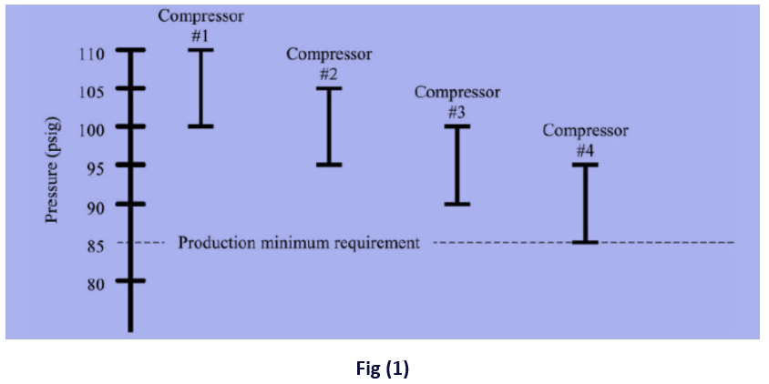
Fig (1) shows a traditional cascaded order of compressors all fixed speed type.
Compressor number 1 is the base load, cutting “in” first and cutting “out” last, with other compressors operating as slaves to operate any time needed.
Cascading, though believed to be the easiest, the simplest and the cheapest way of controlling multi compressors as a group, is however of some drawbacks as follows:
- Delivery pressure range set for any member compressor and the resultant average discharge pressure range of the group, stays higher than what is actually needed- in Fig(1) while the minimum pressure required is 85 psi, the operating range extends up to 110 psi- meaning higher operating cost.
- There is a limit on the number of compressors in the group as any additional compressor causes the average discharge pressure to further increase.
- An operator is required to manually, and at given intervals, assign base load duty to other compressors in a bid to bring all under a similar work load.
- Any compressor sharing the group, either fixed speed or variable with part load (trimming) characteristics, needs to be in good shape and health for a reliable and trouble free operation.
Cascaded arrangement though expects the compressors to preferably be of similar part load characteristics; this nevertheless may not always be the case as variable speed compressors also happen to be present in the cascaded units with their unique part loading characteristics.
As we all know, start/stop is the most efficient operating mode where either the compressors run full loaded with all their power consumption justified or zero loaded with no power consumption at all, this also fully acceptable!
With the above said, and bearing in mind that fixed speed compressors running start/stop may not always be a good choice to adopt, those with high part load characteristics gain more importance.
Though modulation (restricting inlet air to match the demand) could also be a choice for flow adjustment, this however is the least efficient part load operating mode consuming about 70% of its full power any time running with its least intake air and delivery!
Imagine a 55 kW compressor drawing 62 kW from the network runs 10% loaded and pulls almost 44 kW, a huge waste of power.
Variable speed compressors with their highest energy saving characteristics, remain number one choice for part load operation provided they are correctly selected and sized!
What I have heard repeatedly -I wish I did not- is a wrong conception, that; for a variable speed compressor operating part load, capacity does not matter! Contrary to this general understanding, variable speed compressors capacity is highly important as any wrong size unit could prove inefficient and problematic.
One common issue arising from the wrong size selection of a variable speed compressor-deemed to perform part load or trim duty - is known as “Control Gap” resulting in “Fight for Trim” we will discuss later in this article.
Part load and trim compressors
As said before, actually the most efficient operating mode of any compressor is “start/stop” where it runs either full capacity with no waste power, or stops, with no power consumption.
Despite the above advantages, a fixed speed compressor not precisely matching the demand, would need to run with frequent start/stop causing excessive thermal load on the motor, and rapid wear and tear of the electrical components like contactors, etc.
Though a fixed speed compressor could run load/unload rather than start/stop to avoid thermal load on the motor, this however would not be a proper choice either, as unload running is always associated with waste of power which could amount to 40% of the compressor full load power consumption.
Compressors with part load or trim characteristics are deemed to pick up varying load efficiently, preventing fixed speed compressors from unnecessarily cutting “in” and “out” due to the supply to demand mismatch.
With the above said, let us concentrate on “variable speed compressors” as trim or part load units, and study the correct size they need to be, and the consequences in case were sized incorrect.
For simplicity, I will take one unit fixed speed and one unit variable speed -as part load- though there could be more fixed speed compressors cascaded as shown in Fig (1).
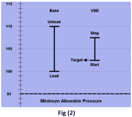
Fig (2)
Depicts
a variable speed compressor operating as part load or trim unit with its
pressure band within a relatively wide range of the fixed speed compressor.
To
better understand the combined operation of cascaded compressors as in Fig
(2) let us start at
a point where both compressors are stand-by, with fixed speed compressor larger
than variable:
- Line pressure falls and the variable speed part load compressor starts and adjusts its delivery to what is needed.
- To meet any demand higher than the fixed speed capacity both compressors feed, with the fixed speed running at its full capacity and the variable speed adjusting its delivery to match the demand
- Demand falls somewhere in between the two compressors capacity, thus higher than the variable speed or trimming, and lower than the fixed speed or base unit:
- Part load compressor reduces its speed/delivery to the lowest possible, eventually turning into load/unload or start/stop.
- Fixed speed compressor feeding more air into the system than actually required, also reaches its set pressure and either unloads or stops.
- Following a temporary halt in delivering compressed air, line pressure falls again, and another cycle restarts right from the beginning with the variable compressor starting first and full speed.
- As seen from the above, for this operating condition -with the demand falling between the two compressors capacity- while the variable speed repeatedly goes from its lowest to highest speed and back, fixed speed frequently loads/ unloads or goes start/stop. This phenomenon where both compressors inefficiently try to perform part load/ trim duty, is known as “Fight for trim” and occurs over a range called “Control Gap”.
To better understand the control gap and fight for trim, let us take a numerical case study as follows:
Case 1
- Fixed speed compressor is 10 m³/min
- Variable or part load is 7 m³/min
- Demand is 8 m³/min (between fixed speed and part load compressor capacity)
Consumer line pressure falls due to the compressed air consumption, variable speed compressor starts first to feed the line but falls short by 1 m³/min (7 < 8) m³/min to meet.
System pressure falls further and fixed speed compressor starts feeding too, total of (10+7) m³/min.
With variable speed compressor even running at its lowest possible speed, system pressure keeps rising and forces variable speed to turn into load/unload, or start/stop operation,
Fixed speed also stops feeding and turns into load/unload or start/stop.
Neither compressor feeding, pressure falls, variable speed compressor takes the trim, or part load duty and a new cycle repeats.
Above situation – with its “control gap” and “fight for trim”, occurs anytime the demand lies between the two compressors capacity as said before.
Let us now see what happens when the fixed and the variable speed or part load compressor are of the same size, with the part load compressor’s varying range smaller than the fixed speed capacity.
Case 2
- Fixed speed is 10 m³/min,
- Part load is also 10 m³/min at full speed, and 4 m³/min at reduced speed (flow change of 6 m³/min)
- Demand is 12 m³/min (between 10 m³/min and (10+4=14) m³/min)
Consumer line pressure falls, variable speed compressor cuts “in” and feeds any demand up to 10 m³/min, but falls short by 2 m³/min (12-10) m³/min to meet the demand.
Fixed speed also cuts “in” feeding 10 m³/min of its own and 4 m³/min supplied by the variable speed.
With (10+4) m³/min, larger than demand, variable speed turns into load/unload or start/stop operation.
Any time the demand falls below 10 m³/min, fixed speed also stops.
With neither compressor temporarily feeding, system pressure falls again and the cycle repeats.
As you might have noticed, though similar to case 1, here also the variable speed compressor repeatedly goes from its lowest speed to highest and back, while fixed speed frequently loads/unloads, or starts/stops, the two cases are however different:
- While in case 1, the situation occurs anytime the demand falls between the fixed and variable speed capacity (7 to 10) m³/min, in case 2 it happens when the demand lies anywhere between the fixed speed + the lowest delivery by the variable speed.
With the above said, the question arises as:
Is there any way to avoid the control gap and the fight for trim?
The answer is yes! All needed is to select a variable speed compressor with its flow adjustment range larger than the largest fixed speed compressor in the cascaded group!
For better understanding, see the numerical case study.
Case 3
- Variable speed compressor is 10 m³/min with a varying range of 8 m³/min (lowest flow rate of 2 m³/min).
- Largest fixed speed is 7 m³/min.
- Variable speed flow range is greater than the largest fixed speed capacity in the group (8 > 7) m³/min.
- Demand is 12 m³/min as in case 2.
Pressure falls, calling on variable speed to feed.
Variable or part load compressor -capable of feeding up to and including 10 m³/min- falls short by 2 m³/min (12-10) m³/min to meet.
Fixed speed cuts “in” feeding additional 7 m³/min, total of (10+7) m³/min by both compressors.
17 m³/min exceeds 12 m³/min by 5 m³/min.
Variable speed or part load with 8 m³/min flow adjustment characteristics, easily reduces its speed to remove extra 5 m³/min.
Flow reduces to lower than fixed speed capacity, pressure rises and the fixed speed compressor cuts “out” first as shown in Fig (3).
Fig (3) arrangement is used anytime the varying range of the part load compressor is greater than the largest fixed speed compressor capacity in the group.
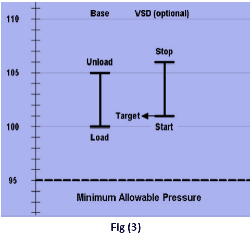
Variable
speed compressor with its stop or unload pressure set higher than fixed speed,
continues reducing speed and feeding any demand down to 2 m
³
/min, without going load/unload, or start/stop.
For any demand higher than 2 m³/min, the variable speed compressor returns quickly to full load delivery, preventing the line or the system pressure from a sensible fall.
To prevent the line pressure from falling in case the variable speed compressor starts star/delta, it is highly recommended to install a proper size reservoir to temporarily feed the system.
As seen from the above, though with varying range of the part load compressor equal to, or greater than the fixed speed compressor capacity, there is neither a fight for trim, nor control gap -as the variable speed compressor always trimming efficiently- this nevertheless does not suggest any selection as in case 1 or 2 is incorrect! All it means is, that; they are not as efficient as case 3!
Before I say “well, guys, this is all I wanted to say” let me draw some conclusions from the article as follows:
- A variable speed compressor is the best choice for part load or trim duty operation in a group of cascaded compressors feeding a common line/system.
- A variable speed compressor deemed to perform part load or trim duty, must be of correct size.
- A variable speed compressor of any capacity will not suit cascaded group of compressors.
- An undersized variable speed part load compressor will not be of any profit/advantage to use.
- A right size part load variable speed compressor must be of a varying flow range equalto, or greater than the largest fixed speed compressor capacity in the cascaded group.
- As a thumb rule, the lowest variable speed capacity for a cascaded group of fixed speed compressors with the largest of X m³/min, is at least 1.5 X m³/min, the larger the better!
For better understanding, let us take a numerical case study:
- Largest fixed speed in the cascaded group is 10 m³/min.
- Part load compressor varying range must be at least 10 m³/min.
- Assuming speed reduction by a factor of 60%, the smallest variable speed compressor needs to be 10/0.6 or 16.6 m³/min.
Though the formula suggests a capacity larger than what an end user would expect, any undersize compressor would be problematic and of no benefit other than its shiny face among the fixed speed compressors!
MULTI COMPRESSORS CONTROL